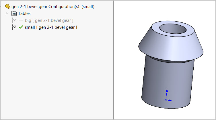
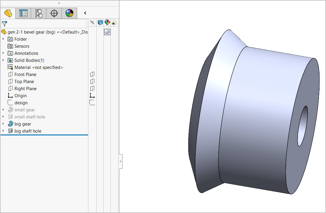
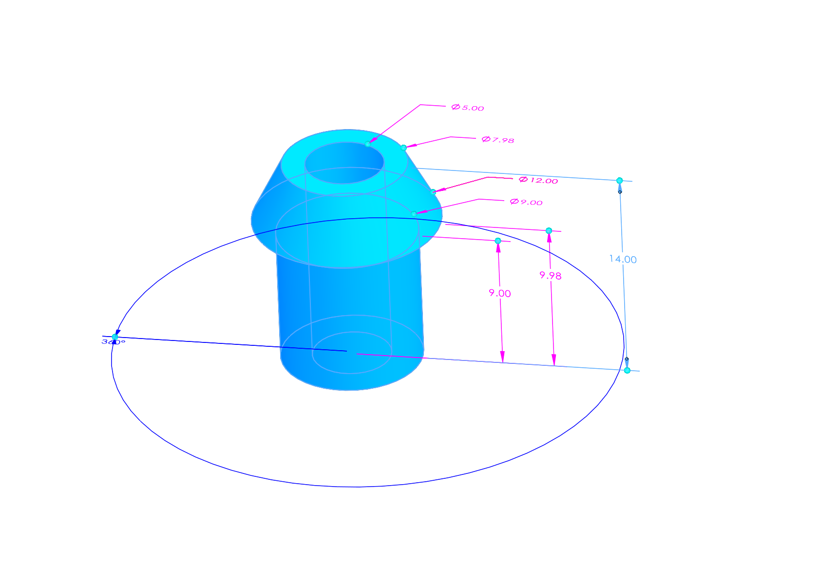
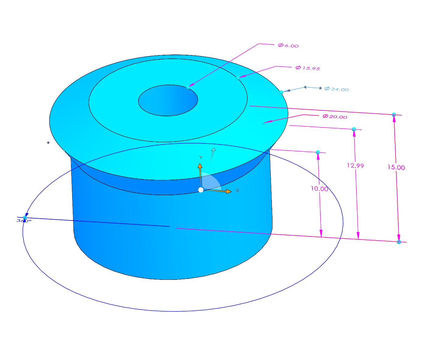
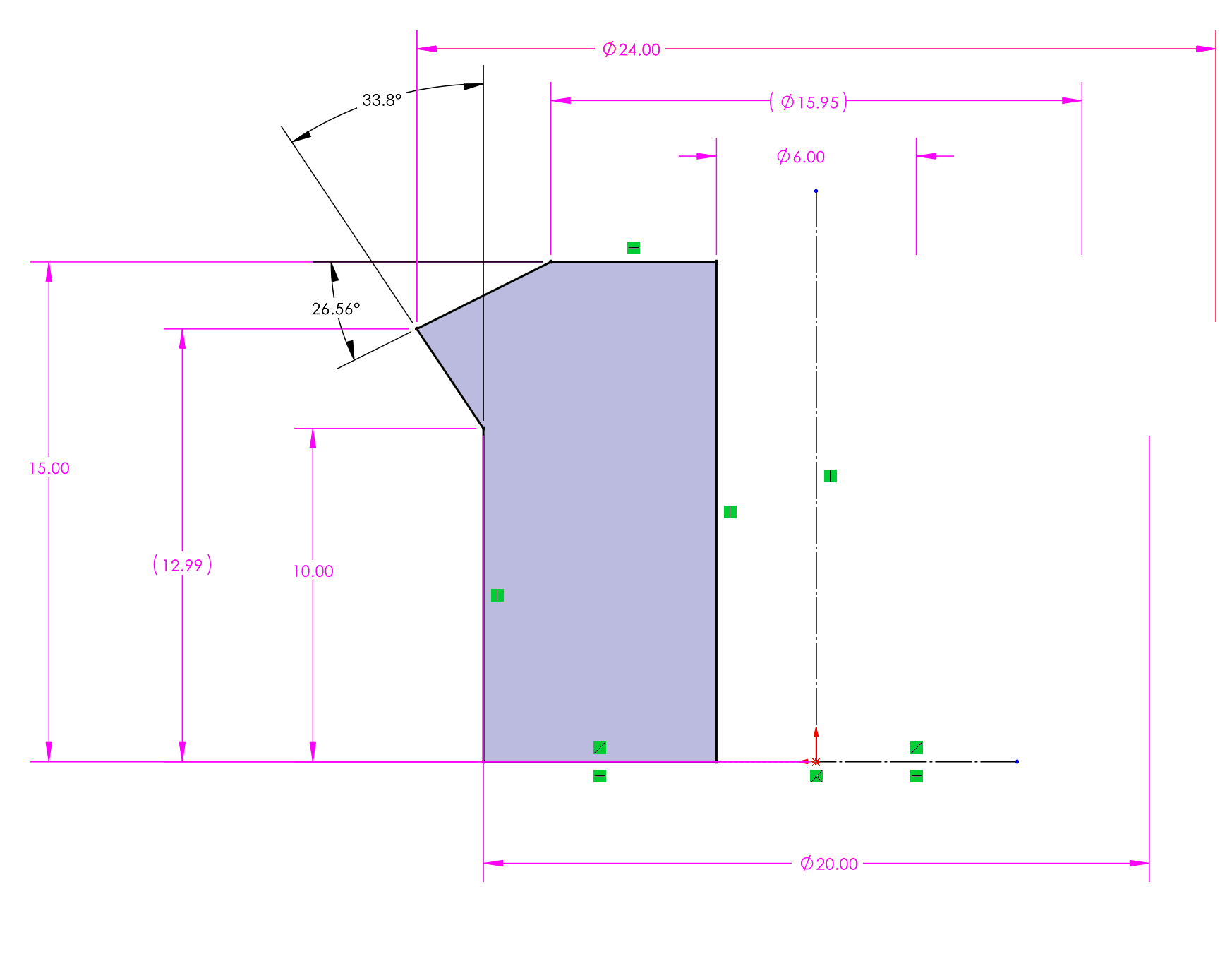
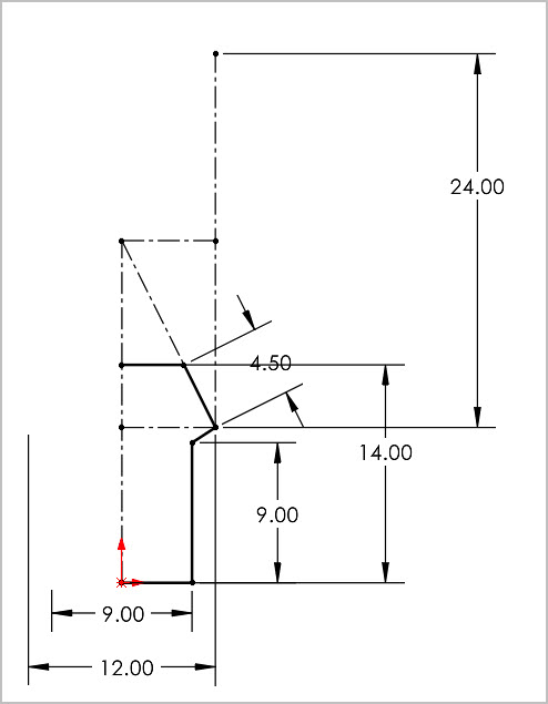
I tried to make a simple, generic bevel gear generator. Its technically not correct, the pitch diameter is the base circle, but the intent was quick & dirty ‘pretty close’ gears & something I can more readily mate. The reference design sketch contains mostly ‘small gear’ specs, but also has related geometry for ‘big gear’. I have 2 configurations, big & small gear which both refer to same design sketch. Each config just hides one or the other. I gave all my input dimensions unique formula names with the plan to now do a design table.
All pretty straightforward until design table time. Using the Excel auto-generate wizard option, it completely skips past the list of parameter names for me to pick from. I’m not sure why. I don’t have a lot of design table experience beyond auto-create. I think there is a manual way too. But just wondering before I go down that path if there is something fundamental I’m missing?
I had a look at your part, and a bit confused with your methodology…
I was able to add the dims into the design table one by one without a problem.
I don’t want to lecture, and you may have a valid reason for doing it in this way, but why not create both parts on a true centerline and make an assembly to locate them?
When I modelled the gears this way, the design table brought in all the dims (attached assy)
I believe it’s not adding all the dims you want due to your modelling methodology; with the both parts’ features in the part, with one layout sketch but the configurations are just suppressing and unsuppressing features driven by the same layout sketch.
Also, with gears, the sketches you’ve done would typically be driven by diameters and angles, not linear coordinate style dimensions
Thanks for your reply & comments. I need to brush up on design table skills, adding in or modifying driving parameters. I rely on auto-create wizard a bit too much.
I admit this was a bit of kludge, not a formal way of making or assembling bevel gears. I tried downloading or reproducing catalog gears, even solid models when available. But the centering geometry was not often present so it was more work to mate them on pitch circle. So I thought develop my own dummy gears approximations based on minimal catalog parameters & easy to mate. Call it maybe 80% of a commercial gear. Because I’m testing many different permutations of tooth count & module, I thought make a single part file with design table.
Example small gear. pd = 15T M0.8 = 12mm. In real life the pd is within the tootnot on the edge like I have it. But this allows me an easy mate on the cone edge. The tooth face 4.5mm is listed in catalog as are the hub dimensions & overall length, so with only a few parameters I have dummy gear approximation. By defining N:1 ratio the big gear pd is 2 * 12=24mm & similarly it can be fully defined with a few more parameters.
To further complicate matters, I expect to be reducing the hub lengths for this application so I need control of that in the table. And in some cases I will have a single big+small arrangement, in other cases 2 smalls at 180-deg with one big… that kind of thing.
I kind of beat my way through sizing, narrowing it down to a few choices so that may be behind me now anyway. But in general SW workflow methodology, where did I go wrong (the worst Haha). Maybe if I had the big gear dully defined in the single design sketch vs defining some parameters in its own part, would that have made the auto-generate design table work? I’ve seen other SW examples where a single sketch drives many parts, but I’m not clear if that’s all within the same file, or there are copies of the file for each part but having the same common design sketch.
Yeah, I understand how sometimes we lead ourselves down the easiest path, which is somehow not technically the best… SolidWorks is built in a way where there is often many ways to skin these cats, for better or for worse!
I think, in the end, if this scenario is an ongoing thing with assemblies where this train is varying often, it would be better to model them properly and add new configs as req’d
If it’s just a set or two, then your method works.
In this case, you could set up equations to drive the assembly mates, and subsequently the driving dimensions of the gears.
The benefits of separate gear parts or configs is that they will come out in the BOM properly, new configs can be added easily, and you can create the 2D drawings from the individual parts easily all with definitive sizing config/part properties automatically.
If you use only separate parts, and do away with configs, you can use a sketch at the assy level to drive the second gear.
All that said, your methodology works OK as a study to size your gears, it’s just not conducive to getting the parameters into the DT automatically.