That is awesome. I always have to go grab my Machinery’s Handbook to look up the values when I have to do a actual cut thread in SW, this excel sheet will be a huge help. Thanks for sharing your file.
Thank you.
I’ve followed slightly different approach. I still had to adjust the pitch though. It supposed to be 32TPI, thus Pitch = 1/32.
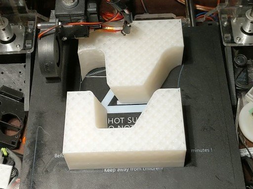
Parts printed on 3d printer came out really good.
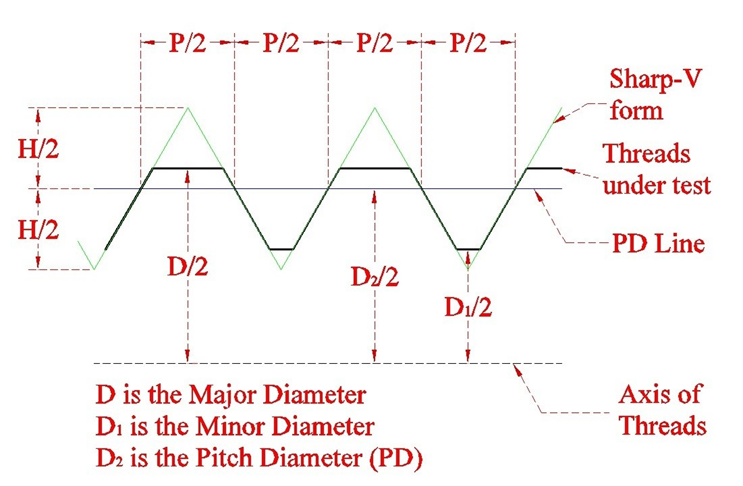
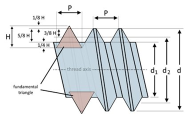
Pitch, Dia and H (which i didn’t need as i had Major dia):
/rant on/
Why , oh why can we not use the cosmetic thread in a consistent performing way in SolidWorks. And why are ISO standards so poorly implemented in SolidWorks Cosmetic thread?
Once, upon a time, when I was in one of the classes at the VAR, actually many times in the past 20 years, we kept asking when? But the VAR just told us, remove the Ø and put the M in place.
For many parts, I create a 100% accurate thread, in the middle of its actual tolerance field. These files are equal in size compared to a part with SolidWorks simplified thread as a feature.
Because the thread is too big for tap and die cut.
Profile milling. ~3 feet diameter buttress.
Need both with proper clearance.
I 3D printed a section to see.
All fasteners from McMaster-Carr also have some other bloat stuff as well, which makes the file open slowly even if you get rid of the threads.
Which is why I cycle everything I get from them through what zxys001 has referred to in the past as a “Parasolid wash”.
Suppress the threads, save it as a parasolid, then open the parasolid and overwrite the original file.
Since Solidworks kernel is parasolid based, then that is all you are doing is stripping everything away that isn’t geometry.
Maybe the biggest cause of bloat in McMaster Carr models is the display properties are maxed out, and the last little bit greatly increases file size. For fasteners, suppress the helix, reduce the image quality (I have a macro for this), and the file size is normal.
If you use a lot of fasteners in assemblies it is worth it to model one of the common sizes you use and use a design table to drive the lengths/properties. I save a ton of time being able to swap lengths using the drop down box.
Seeing as the part seems to be in some form of plastic, most likely the model will be used for the molding, hence the need for the threads in 3D.
This
If you want your part molded or 3d printed why would you not model them. As a mold designer when I get a threaded part to be molded without the threads modeled it’s usually because whomever modeled the part either didn’t know how to or was too lazy to do it. A case of just kicking the can down the road, but eventually somebody has to do it. I agree threads don’t need to be modeled on everything, but not doing them on something you specifically want made to save some file size is just an excuse. It all depends on the part.
Not meant as a shot to anyone, just a slight rant from someone on the receiving end of non modeled threads on parts.
My apologies for the thread drift.