I had watched a video from To Tall Toby a week ago that took a solid & converted it to sheet metal.
I tried to create a shield from a solid but I can’t seem to get it to work without a large relief. Would like the relief to be almost touching to get a smoth weld. Any ideas would be helpful.
Why bother to use convert to sheet metal?
You can model this with native sheet metal tools , and probably you will get better results.
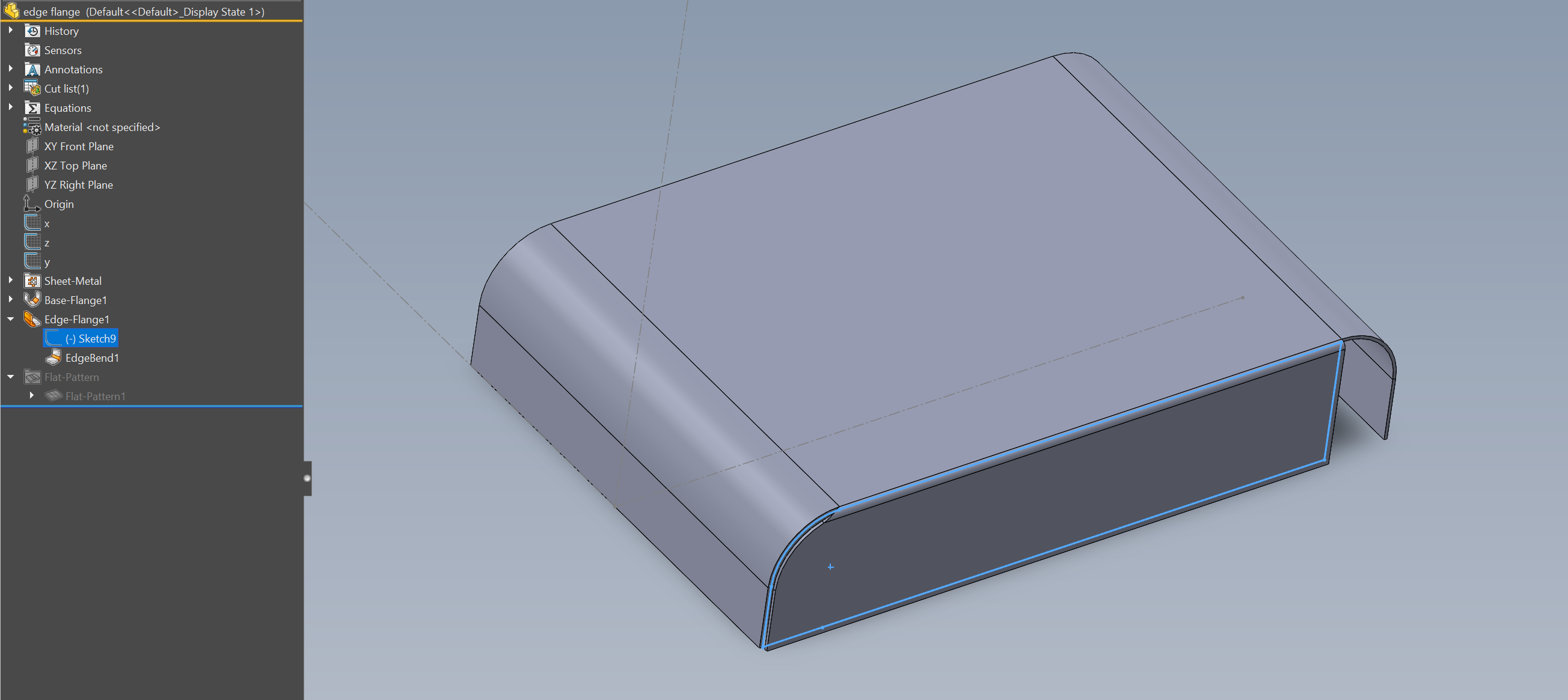
Don’t know how to do that with the Convert to Sheet Metal tool; I think you have better control using Base Flange for the profile and Edge Flange, then you just need edit the Flange sketch as you want:

edge flange.SLDPRT (99.6 KB)
As mentioned… Just model it in sheetmetal to begin with.
Convert to sheetmetal works for basic boxes, and such, but for more complicated things, it’s better to model it as a sheetmetal part right from the start.
For simple parts, as the one shown, I would agree to just model it as a sheet metal part. For more complicated designs (with compounded angles and non 90° bends) I would opt to use the convert to sheet metal tool, and then close the corners manually as required.
ROUNDED BOX.SLDPRT (530 KB)
If you don’t like the auto relief, cut your own.
Defaults are just bad decisions outsourced to software settings.
Can give an example file when you prefer to use convert to sheet metal?
thanks.
I like using convert to sheet metal when I have a shape that is best controlled using a layout sketch. Especially Z-brackets.
I had a job designing hinges for auto interiors. Those designs are best done at the assembly level with master sketches, which are then pushed to the parts. Forming hinge barrels works far better as a sheet metal conversion than trying to use SM features.
my favorite application is when the shape has angles:
Screenshot 2022-02-24 082541.png
If you have to encase i.e. this shape for ducting/piping it’s way faster to ‘link’ all of those parts correctly together with convert sheet metal.
Here a .gif for a more weird shape:
convert sheet metal example.SLDPRT (204 KB)
& attached the part:
convert sheet metal example.SLDPRT
I have attached an arbitrary sheet-metal part where I’ve used the convert to sheet-metal tool. This part can be started and completed with conventional sheet-metal tools (Base-Flange, Edge-flange, etc…), However, in my humble opinion, I find it easier when it comes to using reference geometry to model a solid, versus trying to align the faces and ends of returns and edge flanges to reference geometry, but that’s just me.
SAMPLE BOX 1.SLDPRT
IMAGE 1.jpg
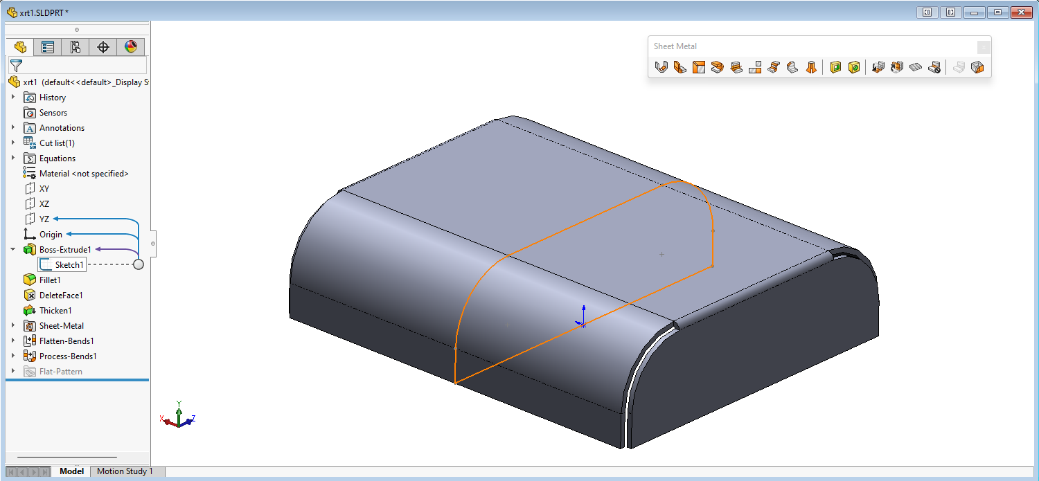
extrude, add radii, delete faces and thicken and create sheetmetal..
xrt1.zip (262 KB)
