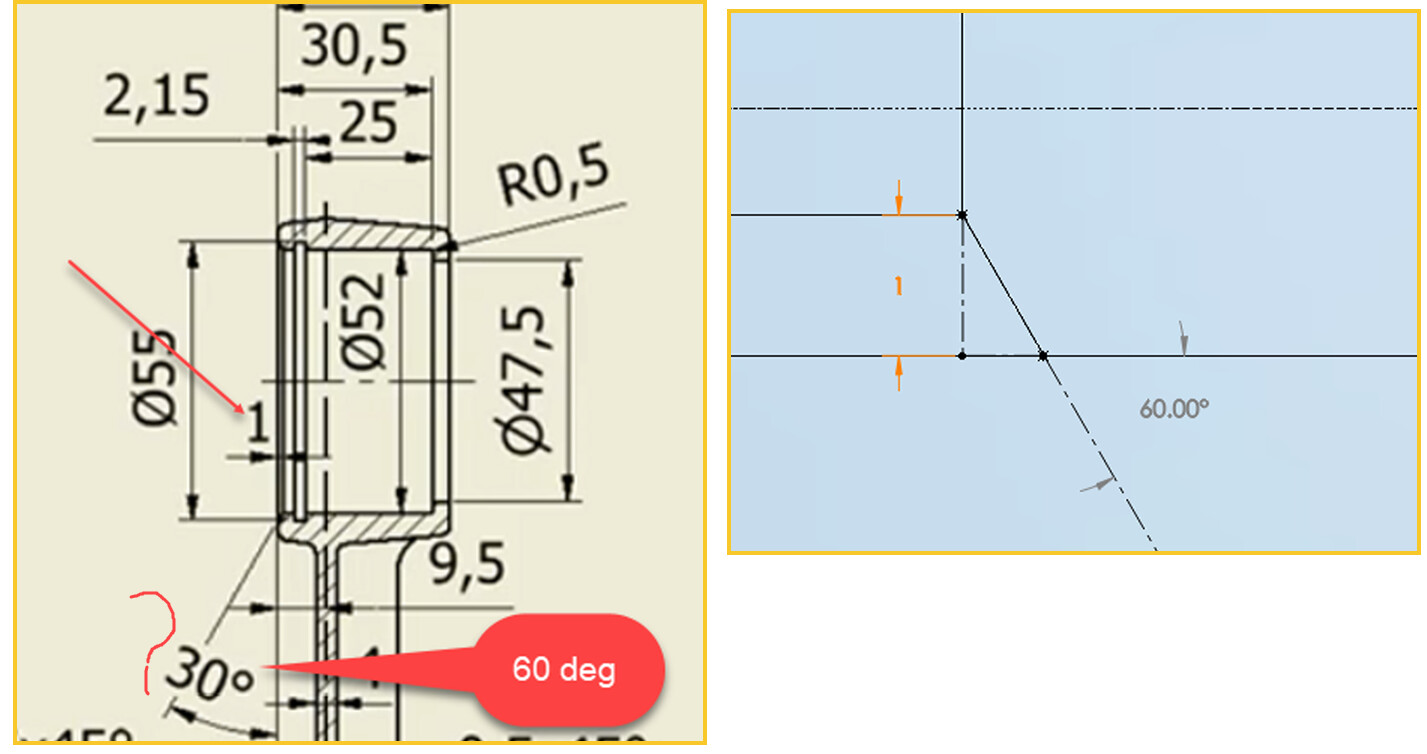
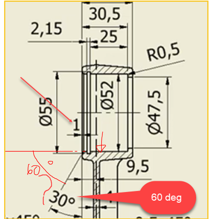
Is this chamfer dimension is correct? Not 30 degree it should be 60 degree for 1 mm depth. In the part file sketch shows in red color.
Piston Rod.SLDPRT (464 KB)
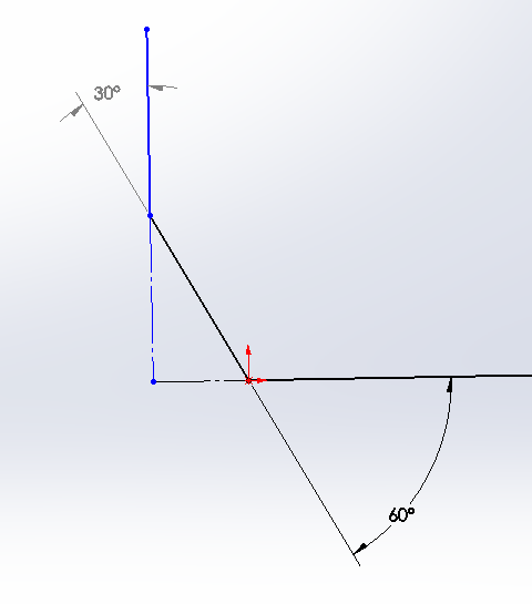
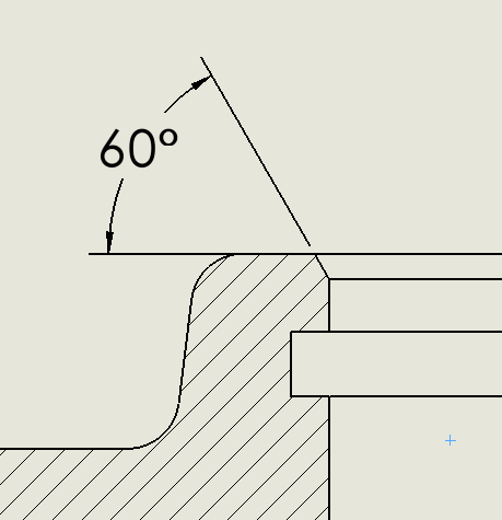
It’s right. The angle I indicated below is 30°.
image.png
@Glenn Schroeder
Diagram shows angle 30 degree measured from the flat face.
The part appears to be wrong. The chamfer feature in the part needs to be changed to 60 degrees if you want it to match the drawing as far as I can tell.
You say this is 60 degree. My understanding is 60 degree is correct.
The 60 Deg you are showing in the sketch is the complement angle of the 30 degree angle that is shown on the drawing. Both are correct assuming that is the type of chamfer you want.
The part you posted has that feature as a 30 degree chamfer which results in a 60 degree dimension as you show in the picture you posted.
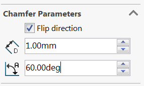
This is how you need to change the settings to get the feature in the part you posted to match the drawing:
Ultimately, no one here can tell you whether the part is correct or the drawing is correct (unless somebody that uses piston rods and knows what fits up against this can tell you). But, they don’t match, and I suspect it was that the feature wasn’t assigned correctly.
Is there a way you can sort this out?
The way I’m looking at it the Part and drawing match. No one here can tell him whether the chamfer is correct or not.
I think what a lot of us skipped over is that which I bolded and underlined, and that is most likely Maha’s original questionning.
I do not have the answer though.
I don’t understand Matt (hey we disagree, must be over my fever…). My take on it is that the drawing clearly doesn’t match the part.
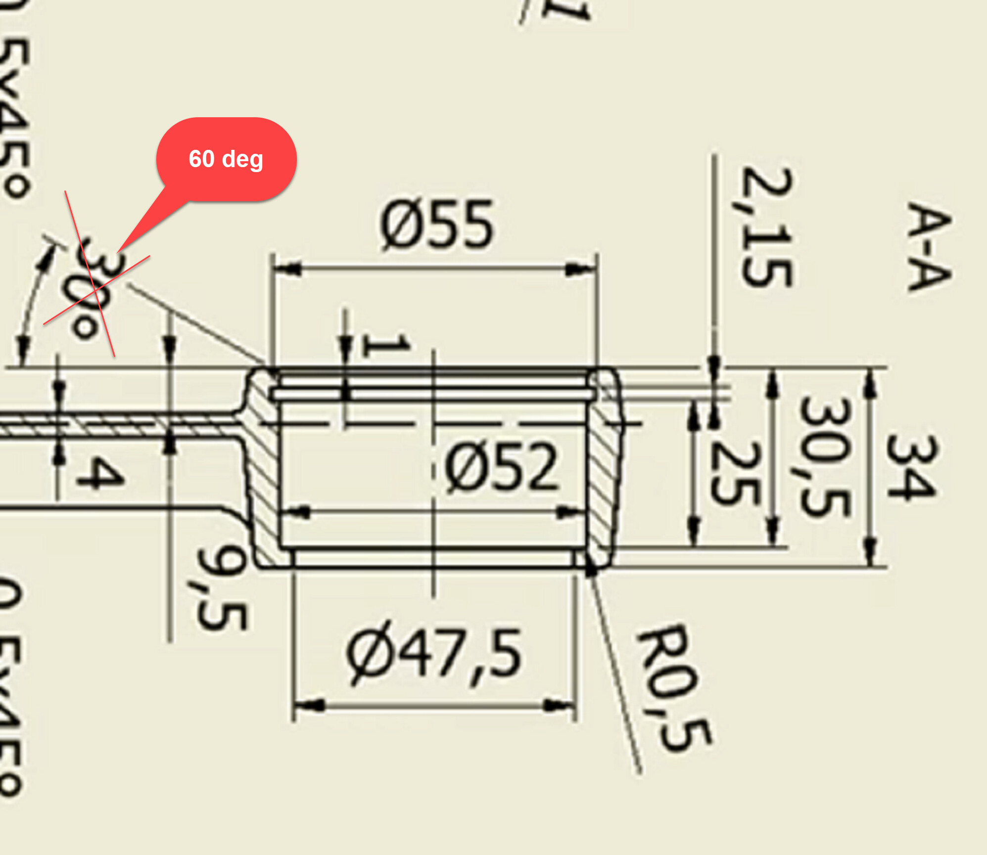
The dimension from the horizontal face to the chamfer is 60 degrees in the part, but 30 degrees in the drawing
image.png
vs:
Red line represents the 0. arrow represents surface the dimension is taken from.
Where are you getting the picture you show at the top? The pictures I’m seeing are not that clear. The picture that the OP posted appears, to me anyway the way it looks when I download it, to have the chamfer going the other way than what you have in the top picture.
so you’re saying the two pictures in the OP are 90 degrees to each other? Again, hard for me to tell since the drawing picture is pretty fuzzy for me. The drawing, again as far as I can tell, appears to have the 60 degree going the other way and then the two would match. If indeed the angles are switched then I would guess someone picked incorrect geometry to get the angle on the drawing.
It’s a little “free of interpretation”, until Maha adds more details.
Okay I can understand now. Drawing is correct, it shows opposite to PM angle, where as PM shows exact angle, both of these angles are equal. I do not know how they call this equal angle in English because my mother tongue is not English.
Careful Maha Nadarasa, check that dimension dialog carefully. The only combination that will get you what is shown in the drawing is this:
image.png
The reason you have to use 60 degrees is because they dimensioned the other dimension for the chamfer as 1mm in the vertical direction. SW uses horizontal, and that’s why you have to use “Flip direction” and 60 degrees.
Take a look at the result and compare it to your drawing:
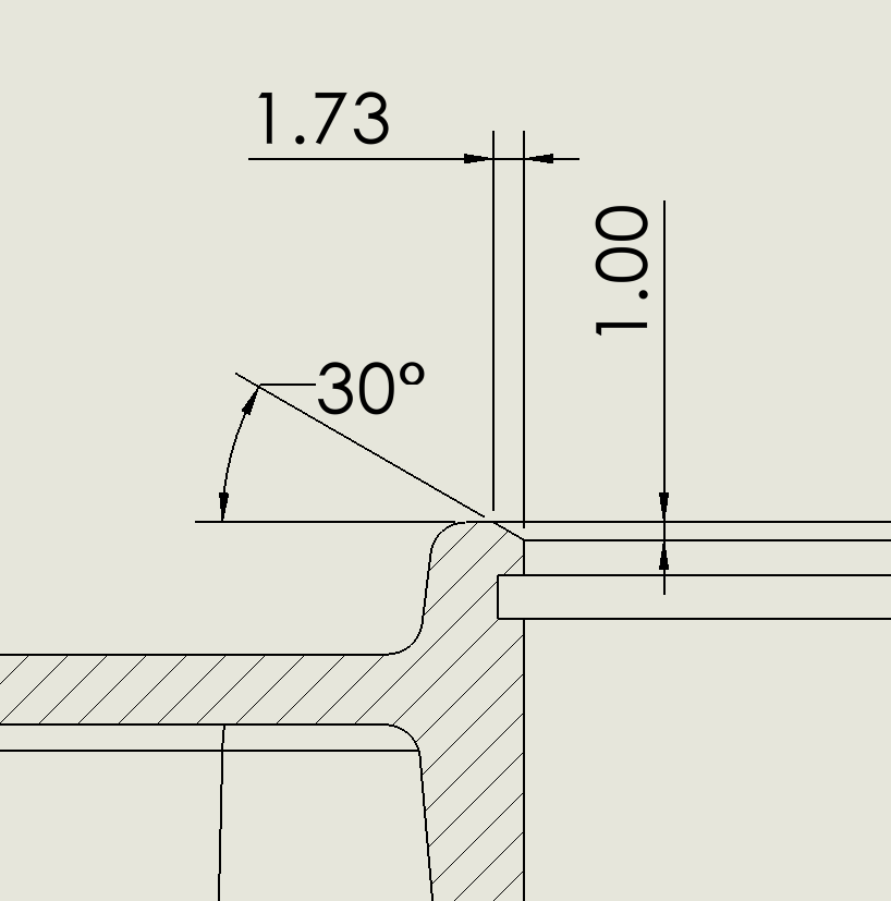
What you say is to get the vertical dimension 1 mm as shown in drawing you must have a horizontal dimension 1.73 mm.
Yes what you’ve posted should work, but you must also uncheck the “Flip direction”. So, yes there is more than 1 method to get it to show correctly, but what you posted requires calculating that dimension (1mm/tan(30deg)).
Thanks for clarifying the issue.
Why not make it 45°, then it doesn’t matter which side its measured from.