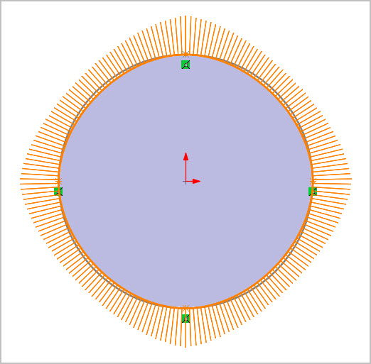
Kind of a weird question of no particular value other than I stumbled on it. Is there any parameter that can be defined in a spline to ‘make’ it a circular? (Other than, I assume, using equation driven splines). As a visual check I drew a circle, then made a spline intercepting the quadrant points. Its close but obviously not exact. Once closed at the 12:00 quadrant seems like I can’t force any other constraints to improve it.
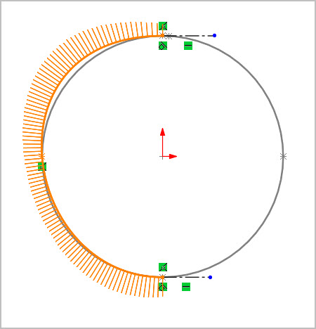
Interestingly if I spline through half a circle using 3 intercepts & constrain the 2 ends tangent to horizontal lines, its actually not symmetric top to bottom
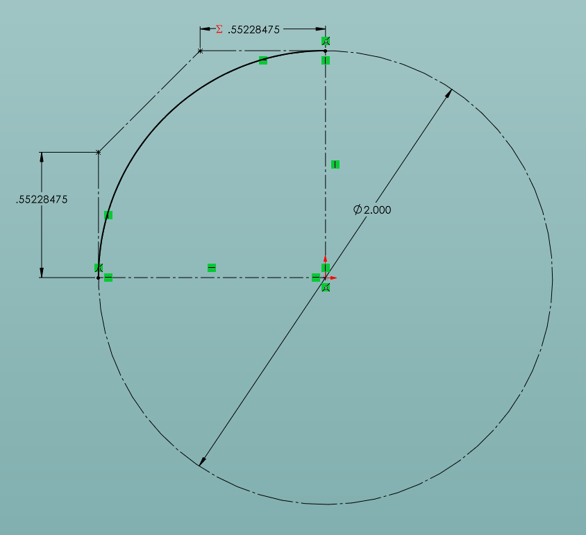
No. SOLIDWORKS splines are either B-splines (basis splines) or Bezier curves (style splines), neither of which can represent a true circle. You can get a close approximation with four Bezier (style) splines where you place the control points on a line tangent to the ends of the spline and at a distance of
\frac{4}{3}tan(\frac{\pi}{8}) multiplied by the circle radius.
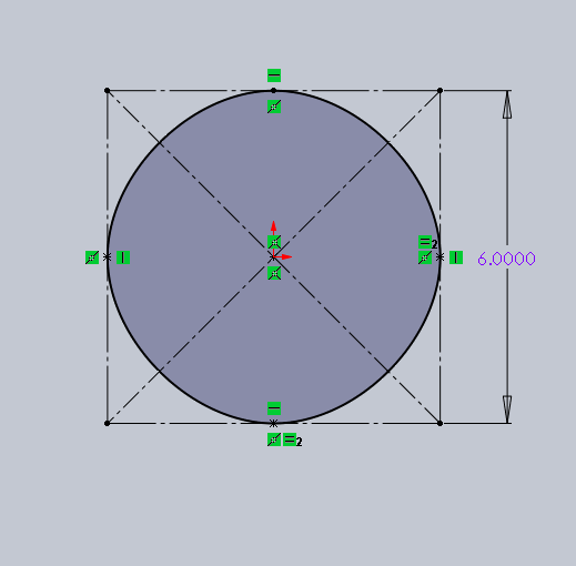
How close is this? I first drew a square, and then placed the control points for the spline on the center points of each side. It immediately turned black, without me adding any additional restraints.
But anyway, splines do have a specific mathematical definition, and there is no way to take the variables/constants of that math and make them be the equation of a circle. As shown, you can get it pretty close, but never exact.
How close do you need to be? What is the purpose of trying to make a circular spline?
Since this whole thing is a mental exercise anyway… I wonder how many different ways the error could be evaluated…
Ratio of un-shared volume to the volume of the circle?
Just the area of both is a poor evaluator. You can easily create a square with the same area as a circle. I think any evaluation based on area would need to account for shared vs unshared area.
Thanks for replies. The quadrant (only) result was interesting, I will have to play with this more. And this mostly explains the non-symmetry issue.
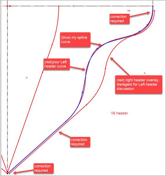
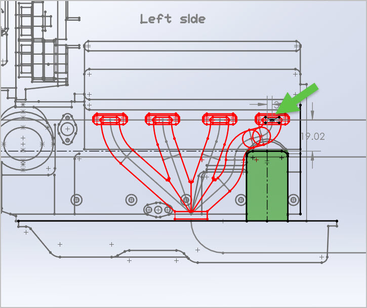
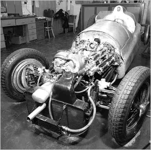
There actually was a practical, more interesting purpose behind the scenes. Its not like I’m a spline nerd LOL. Reproducing headers for a model of famous vintage racing engine from limited side & front views. After some corrections I made the curvy part within (blue) pipe path as spline. It was pointed out to me that back in the day they would have welded from sticks of straight or curve segments (red) which would have had joints & seams in slightly different positions. Nobody is getting fussed with the end result in this case but why I wondered out loud if there was a way. I may have been closer than I thought because I was picking the 3 ends & center of the circular arc section.
This is why we don’t use splines for formed tubes. Fabricated tubes of straights and mandrel bent angles would be same. 3D Sketching in SW is pretty nice IMO. I would forget splines for that application.
Do you know if they matched primary lengths? If you’re working from 2D / image you could adjust the 3rd dimension to balance the lengths. Just a thought.
In short, yes. The start/end points & various other datums surfaces are quite well defined, but the exact header path was I suspect mitered & welded in-situ to thread through various other obstructions. And of course real life issues like how to get the welded assembly on & off or get a wrench on the nuts. Documentation is scarce. Some of the FS pictures I saw, had obvious ‘persuasion’ marks on various piping that must have been too close to something else, but they did what they needed to do. It’s just mind blowing to me what people achieved back in the day without CAD (or computers or calculators or…). No shortage of smart people & dedicated effort. I don’t want to mention too much about the model project because I’m just helping the originator, but the FS is a Mercedes W165. Fascinating story.