Barrel hoops as adjustable part?

I’ve modelled hypocycloid engine, using plans from here, and most of the parts are fairly

straight-forward.

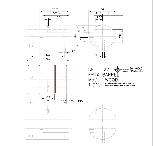
But, I was wondering how to approach modelling hoops for the faux barrel.

As you can see in the drawing below, there are 4 of them, going around oblong(?)-shaped barrel.

The question is, how do I setup hoop part so it adjusts to the geometry of the barrel

when I insert it into sub-assembly?

Dimensions given for it are, apart from sheet-metal thickness(2mm), reference circle diameter.

Videos I’ve watched, AFAICT, cover ‘spring as variable part’ use-case, but I have no idea if that applies here.

Adjustable Parts require a set of specified variables that are given values when placed in the assembly. How those variables are given the values varies based on what you want but can be any of the following: An assembly variable, a manual measurement, a keyed in value. For your assembly I would recommend placing a PMI dimension to get the diameter of your cylindrical part and then use that as the Variable to pass to your band. It will update as the cylindrical part changes size.

Master Skeleton

SSP

make the parts in the assembly.

Thank you all :slight_smile:

I’ll try what @KennyG suggested, and do some research on @Frederick_Law idea, I am not

familiar with ‘Master skeleton’ work-flow.

@David_Matula Model them in-context?

That was my initial idea, but one of the points of the exercise is trying new approaches/learning something new :slight_smile:

Thanks again.

Master Skeleton

Master Sketch

On simple assembly, 1 Master sketch control everything.

The Master Sketch is first part in any assembly and everything constrain to the sketch.

Purchased parts or reference parts can go in a Master Assembly with Master Sketch to create projected lines/sketch in the Master Sketch.

Different conveyor config from master sketch. Just change parameters and update. It did need a few different Master for some different config.

Solidwork config and latest IV ModelState could eliminate that.

https://www.autodesk.com/autodesk-university/article/skeletons-in-the-closet

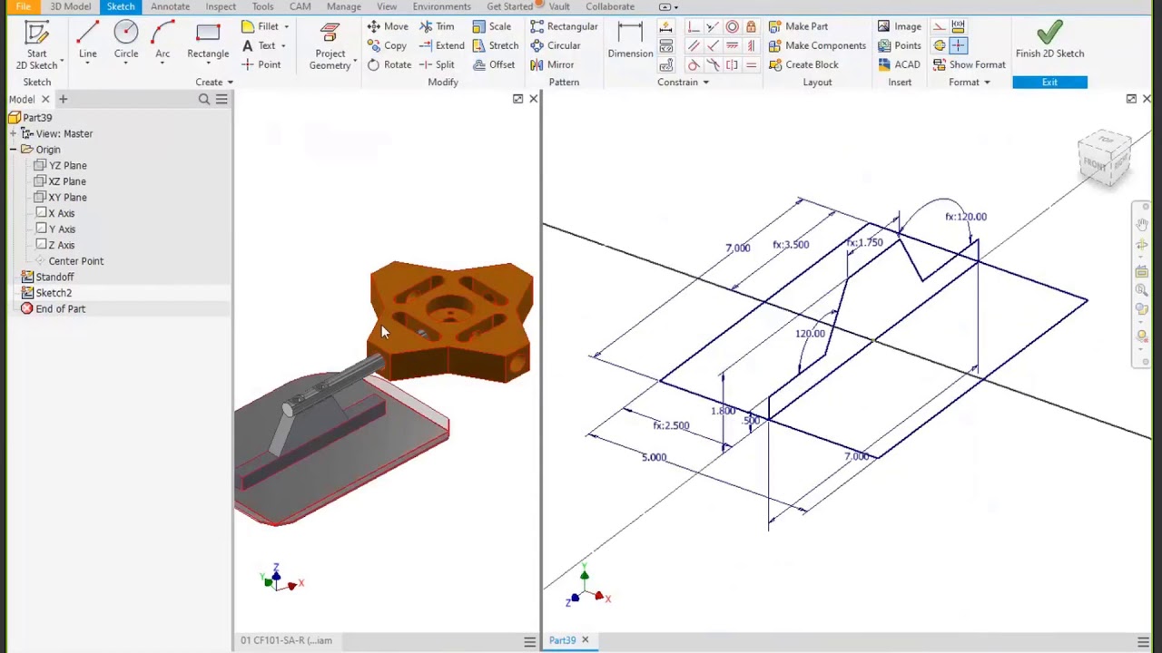
It is very tempting to use 3D sketch but don’t. Use multiple 2D sketch and project construction edge/line/profile.

SolidWorks love to change and rotate sketch around 3D line. Every time it update, everything will rotate.

Just an FYI, this is a Solid Edge group, not SolidWorks. (for our SolidWorks friends who seem to forget sometimes :grin:)

Never mind, I’m the elephant in the room :elephant:

SSP modeling is not limited to a particular platform.

Build the inner parts in an assembly insert a new part edit the part then copy the outer body surfaces into the new part patch one end of the split surfaces, then trim it to the hoop width the convert the surface to sheet metal. every time the inner body is changed the surface will update thus up date the hoop.

Model the barrel as you want it (after all its the “driving” part).

New file and part copy of the barrel as construction body. Surface → extrude → include the outer edge of the barrel → thicken… and add whatever extra you want to add.

This workflow is only valid in ordered mode if you want it to autoadjust.