So I do have a coordinate system that is defined totally random. Sometimes with 1 or 2 edges/axis - another time with nothing but a vertex a third time with faces…
How do i add an actual axis to this coordinate system with a macro? I’d like to add all three of them. Can I somehow use the ICoordinateSystemFeatureData Interface Members to do that? Any ideas?
I have made part templates with X, Y, and Z axes so they are in there at the start. They are made from the intersections of the planes or the origin and perpendicular to a plane.
I’m not a macro person, but. . . Could your macro be based on picking a vertex, running the macro and it make axes through that point and perpendicular to the primary planes? Is that what you are trying to achieve?
Ah, that helps.
So adding a coordinate system to a point only moves the origin to a different point.
Now I have a better idea at least. It would mean though to analyze how the coordinate system is aligned and use those same selections to make axes from that.
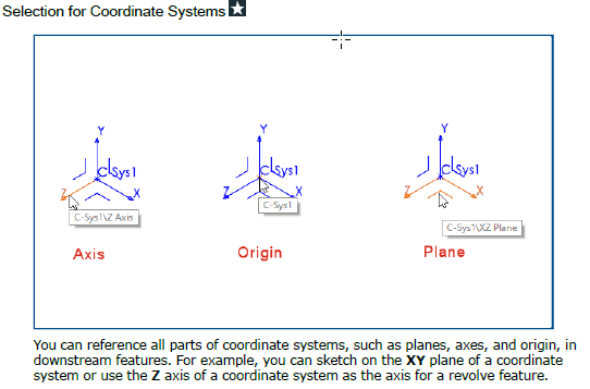
ICoordinateSystemFeatureData can be used to get the points, faces ,edges the CS was build upon.
Because you can have multiple ways of defining things, it can be challenging to filter out the right information. But if you restrict yourself to selecting only points for instance, you could get those and combined with the origin, you could create an axis with 2 points.
Can I ask for what use case you need those axes? Is it for mating components? In that case if you mate a component origin to a CS all axes are aligned accordingly. An origin is just a special CS (that can’t be deleted)
I was looking into an easy ‘all in one’ solution:
We have to set a coordinate system for many parts for our CNC.
The grain direction is the X-Axis of the new coordinate system.
And if we place it properly, we can also want to use the planes from this coordinate system.
I was hoping to only change the position of the coordinate system to also move 3 planes, 3 axes with it & use this reference geometry additionally to the standard ref. geometry.
This would lead automatically to using more ref. geometry when mating/using features etc.
And changing it should be as easy as only changing the orientation of one coordinate system, but…it seems that this is not possible in an easy way. What a shame this is…
Do you need the CS for your CNC (in other words : can your CNC import the CS?)
or do you only need a point, 3 axes and 3 planes in you CNC environment for easy selecting, aligning?
If the latter you could create a dummy part with a point, 3 axis, 3 workplanes ? Or just a 3Dsketch with 3 lines.
Or even better make that a macro feature.
Another thought: if you place your CS. You could create a macro that positions your part by moving all the geometry(move body) as if the CS becomes the origin. (The CS has a transformation matrix with the needed translations, rotations)
Depends a lot on which entities your CNC environment can import.
Back when I was trying to get SW to work the way NX did, I created a “Part” that was nothing but a coordinate system. It is essentially my part template, which has the 3 axis included. Instead of inserting what solidworks calls a coordinate system, I would insert this part. Maybe you could write a macro to place a copy of the part at each instance of a coordinate system?
We have to place the coordinate system on probably 60% of our parts - so only placing this would be the preferred method.
Yes, we ‘only’ need 3 planes, 3 axes and the coordinate system point in there.
I thought about a macro but this coordinate system can easily change (regularly: flip Z-Axis or change X-Axis/Y-Axis or change coordinate system point) and since I cannot really link everything it will imho get too unstable (i.e. person A changes this with the macro, yay - person b changes anything (planes, axes, coordinate system) not with a macro & nothing changes with it (yikes!)).
Soooo… I’ll delay this one for now. Maybe at a later stage.
I still cannot believe, that this is not integrated into SolidWorks. <()>
[quote=“mike miller” post_id=13331 time=1633355765 user_id=118] @SPerman, can you elaborate on this? I’ve never gotten into coordinate systems very deep, maybe that’s why I don’t see a huge benefit…
[/quote]
We used coordinate systems the way IV users use skeleton sketches.
Our top level vehicle was nothing but a collection of coordinate systems. The chassis was locked to the chassis coordinate system, the body to the body, engine, etc. The body assembly would be built the same way. Here’s a coordinate system for the front glass, one for the roof, one for the hood, etc.
We made carbon fiber tubing ducts that pulled air out of the quarter window and fed the brakes, or rear gear cooler. Those had to route around the roll cage as well as stay out of the drivers view and not run into any other obstacles. Coordinate systems were used to create the path for the tube to follow. Add fillets and every intersection and do sweep. If you need to make an adjustment, just change a dimension for the appropriate coordinate system and everything related to that CS updates (including other CS.)
You can use CS to define the geometry of your part. So once again, you move a CS and everything related to it follows.
They also had polar coordinate systems, if you are into that kind of thing.
I just cannot believe that you cannot access this somehow. The vector has to exist somewhere so that SolidWorks can use it. Every single triad uses the information from the standard origin - and the other coordinate system is just a transformed one. I need an SPR for that. SWX 2022 SP5 could have it.