So, there was a post at the old forum, but since it’s lost in the platform I figured I’d recreate it.
I have attached my version that I created 7 years ago. So, it can be opened by just about anyone…Though, I think it breaks if you change the parameters too drastically, even though the equation should be correct. It’s been a little while (7 years) since I’ve messed with this model.
Hey DennisD and Conklin,
I believe you had even better models. Want to add them here?
Thanks for sharing. Very appreciated!
mattpeneguy, I had used the involute equation curve, but abandoned it because I wanted more control over the geometry. In particular, I use gears with a profile shift and found it much easier to accomplish with my involute curve.
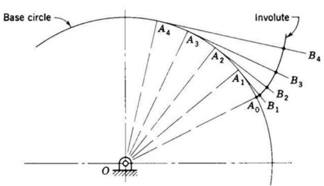
Attached are files I developed using the geometric definition of an involute curve where the arc lengths, A, equal their unwrapped lengths, B. This capability (setting arc lengths equal to straight line lengths) became available in either SWX2015 or SWX2016 and really simplified the models. I just updated these files so they are saved in SWX2021.
image.png
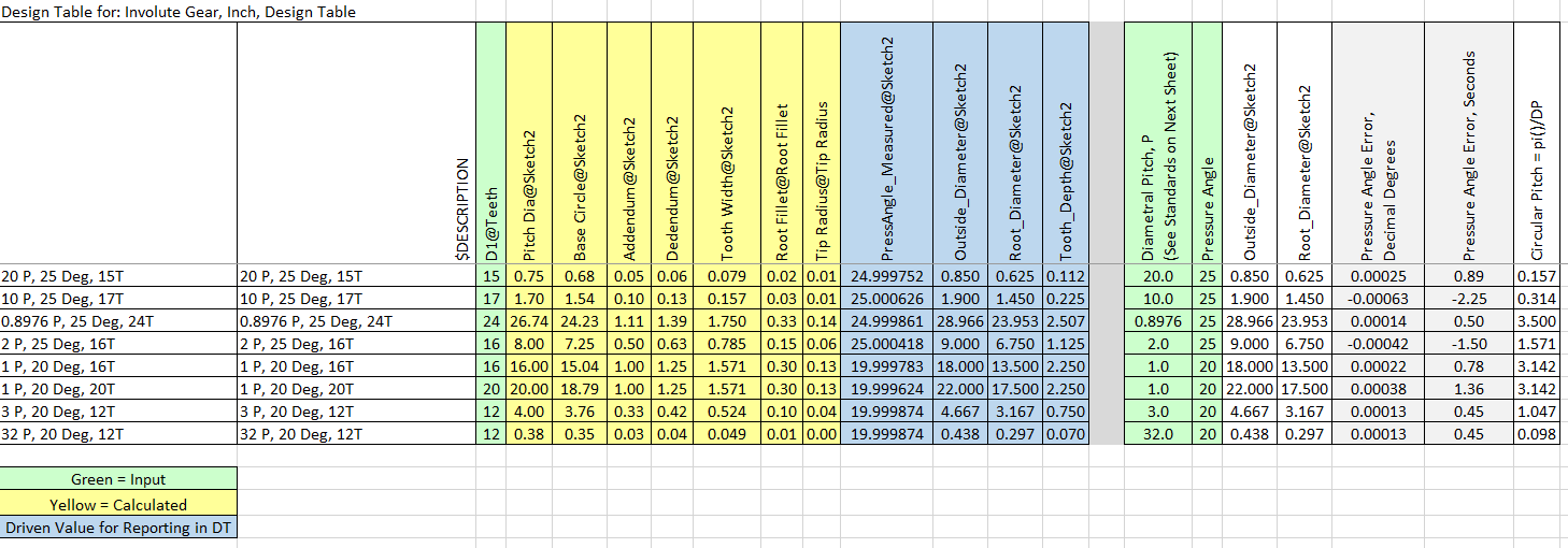
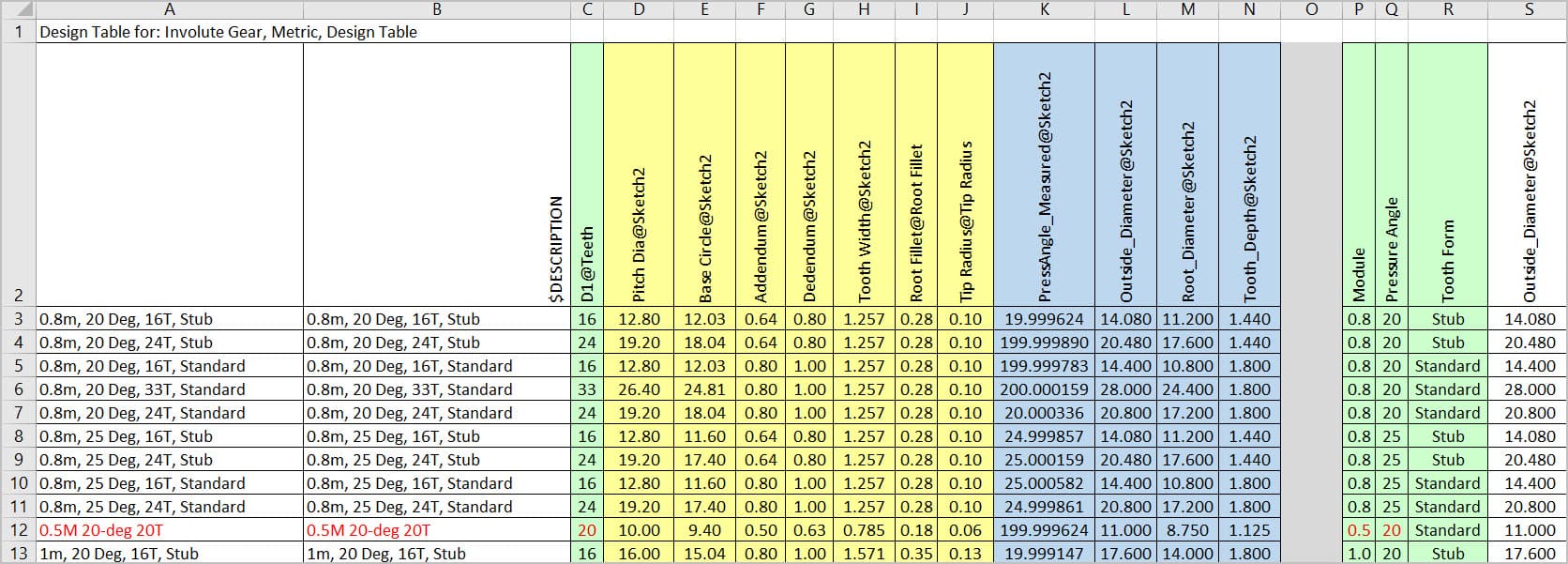
These gears use a Design Table where you input the number of teeth, pressure angle, and module (metric) or diametral pitch (inch). They are very good for the involute profile.
Caveat emptor (Disclaimer):
These models DO NOT deal with undercuts that would occur when there are few teeth, and specifics of the root and tip radius are up to the user. They are offered simply as a good starting point for someone, but the ultimate responsibility is yours in using these models. As with threads on a fastener, often times it is unnecessary to model something with such detail, since the specification governs and not the geometry. However, since these models are easy to use for any straight gear I need there is no downside, plus they are great for 3D printing or even FEA if undercuts and radii are properly done.
If someone would like to make helical versions of these and share them here that would be great. I have not done so simply because I have not yet had the need.
I invite you forum members to also contribute more advanced parametric gear files, in particular bevel gears, spiral bevel gears, worm sets, and profile shifted gears. Profile shifting is an art unto itself and, like bevel gears, requires consideration of the mating gear.
BONUS Design Table Feature:
Normally a DT only includes the configured parameters that control the configuration. I discovered that DRIVEN dimensions can be displayed in a DT. All you have to do is paste the parameter into the next available active column. SWX will automatically populate the values when the configurations are rebuilt. This is sometimes handy when you are developing a part and want to see the result on a parameter. In these files I used a driven dimension to measure the resulting pressure angle. Note that the values in the DT only update if the configuration has been rebuilt. These driven values are shaded blue, with inputs in green and calculated driving values in yellow. Note that some of the inputs are not direct SWX parameters, but are instead used in the calculating driving values SWX is using in the model. Gotta love the ease of use of Excel!!
The DT’s in these files also demonstrate how a blank row and column cause SWX to ignore anything below the blank row and to the right of the blank column. This is handy for notes, drop-downs, scratchpad calculations, etc.
image.png
Involute Gear-Internal, Metric, DT 2021.SLDPRT (2.71 MB)
Involute Gear, Metric Spur, DT 2021.SLDPRT (3.3 MB)
Why oh why did you upgrade them to 2021?..We’re on Windows 7 here and can’t install SW 2021…
Thanks for sharing them, though. I’m sure others will get some good use out of them.
Well, the files I posted are the best polished versions I have and include inch and internal versions.
I just did some digging and found one of the early version files in SWX2016, but it is only for a metric spur gear. Also attached is the collection of inch/metric, internal/external gears last saved in SWX2019.
Enjoy!
Internal-External Gear Collection 2019.zip (4.85 MB)
Thanks Dennis!
Thanks for sharing. Files that supposed to be saved in SW2019 show future version when opened in 2019. Could you check, Dennis?
Sorry about that. I verified that these were last saved in SWX2019.
Involute Gear-Internal, Metric-2, DesignTable 2019.SLDPRT (1.13 MB)
Yes, these are. Thanks again for sharing. ![]()
Thanks for sharing!
I found this tool at Grabcad.com.
Does anyone know this tool or does anyone even use it?
I have posted a wile back this file
“Robust Involute Spur Gear Generator - Better 02.SLDPRT”
A “GRABCAD” link to it it here:
https://grabcad.com/library/robust-involute-spur-gear-generator-solidworks-1
it has been downloaded a “few” times and has gotten good reviews…
I think they were saved there as Solidworks 2015
We have an old chain driven machine that I’m trying to reverse engineer some parts to possibly replace. One of them is a 15 tooth pinion. Sooo, that means undercut is present. I don’t think the original gear set was profile shifted, but we need to get some better pictures of the rack gear, which appears to be the original. The machine was crammed in a corner and we didn’t have a lot of access. It’s only 3 miles from the office, so it wasn’t a comprehensive teardown. We just wanted to get an idea of what we’re dealing with.
So that brings up undercutting of the pinion to eliminate the possibility of interference, which I don’t think either DennisD nor Conklin account for in their models. That’s partly because nobody should be designing such gears. If you need fewer gear teeth then profile shifted gears are a better solution than undercutting…And ultimately that’s probably what we’ll suggest for the gear set. But for the time being I need an undercut pinion gear.
Long story short I found this site where you can create them and convert the set over to CAD:
http://hessmer.org/gears/InvoluteSpurGearBuilder.html?circularPitch=8&pressureAngle=20&clearance=0.05&backlash=0.05&profileShift=0&gear1ToothCount=150&gear1CenterHoleDiamater=0&gear2ToothCount=15&gear2CenterHoleDiamater=0&showOption=3
When I get some time I may figure out the math behind the undercut process and maybe we could add it to one of these gear models?
mattpeneguy What are the particulars of the gear besides number of teeth (pressure angle and module or diametral pitch)? 15T is not necessarily undercut, but if it is then yes, that is a different geometry than the files I created. I am interested in learning more about this so I could add that feature. Keep us posted with all that you learn.
Hello. I downloaded your file but I’m having a problem trying to generate a module gear. I’m sure I did successfully this before. So either I forgot how, or maybe I never checked it too rigorously at the time.
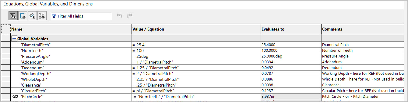
Your part template is default IMP which I left as-is for now. I think the issue is how I’m trying to enter the equivalent diametral pitch in Equations panel or maybe overriding the units is breaking something. I Googled Diametral pitch conversion formulas & but obviously missing something fundamental.
For example a 20 tooth x Module 0.5 gear x 20-deg pressure angle should yield a 10mm pitch diameter & OD of 11.0mm. I cant seem to generate anything close to that. Can you (or anyone really) please show me the required conversion step and/or screen grab of Equations input that yields these example results?
Rather than using @Conklin’s imperial version, scroll up and use @DennisD’s metric version. It’s been a while since I looked at it, but it worked when I used it. I don’t think SW would do anything to break it, but who knows.
You can also use the link in @Hansjoerg’s post as a quick check, but you’ll have to convert the SVG to DWG or DXF before importing it into SW.
Thank you for mentioning this! I just skimmed the post because it originated quite a few years ago. When I recognized the aforementioned GrabCad model I juts focused on that. The Metric DesignTable 2019 model is a gem. I just created my own configuration (red=input). It seems to check out just fine for my purposes.
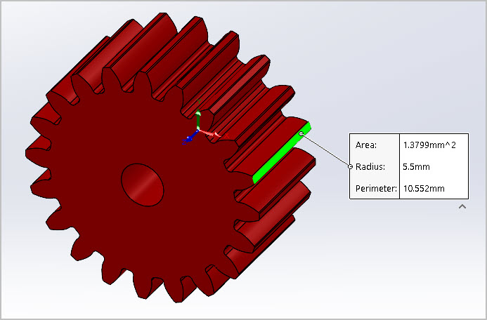
I went back & read the DennisD explanation regarding choice of involute generation & clearance caveats. Perfectly fine for my purposes at present. I’m not making gears, just wanting to something more accurate for my assemblies. Some of the online services are Ok if your gear happens to match what they sell, but not very useful if you have something different. And some are just plain wrong.
Somewhat related, I found these YouTube videos, appear to be part of an engineering course saved online. Interesting tutorial & quite a thorough workflow. Apparently there are gears and there are gears. Seems like once you get into more critical gear parameters and/or particular pinion/gear relationships, other issues rear their head & need to be compensated for. He writes an explicit formula for involute & discusses pros/cons in that regard.
I suppose if you want ‘real’ gears you have to buy a plug-in module where all this is dealt with, or write your own code. I’m very thankful the individuals mentioned in this discussion took on the challenge.
Video Titles
Modeling an Equation Driven Involute Spur Gear in Solidworks
2014W ENGR380 Lecture16 Introduction to Gear, Part II