I have some piping model based on a centerline 3d sketch route.
I would like to avoid drafting and I could give my shop floor the part list and a simplified 3d with balloons with straight pipes length indications, and the centerline sketch dimension over the 3d.
is it possible to use a 3d sketch dimension to be visualized with edrawings (as native sw file or exported edrawings file) like it was a MBD or as an annotation without drawing them twice?
we do not have MBD license, the money to buy it and we do not need all MBD features
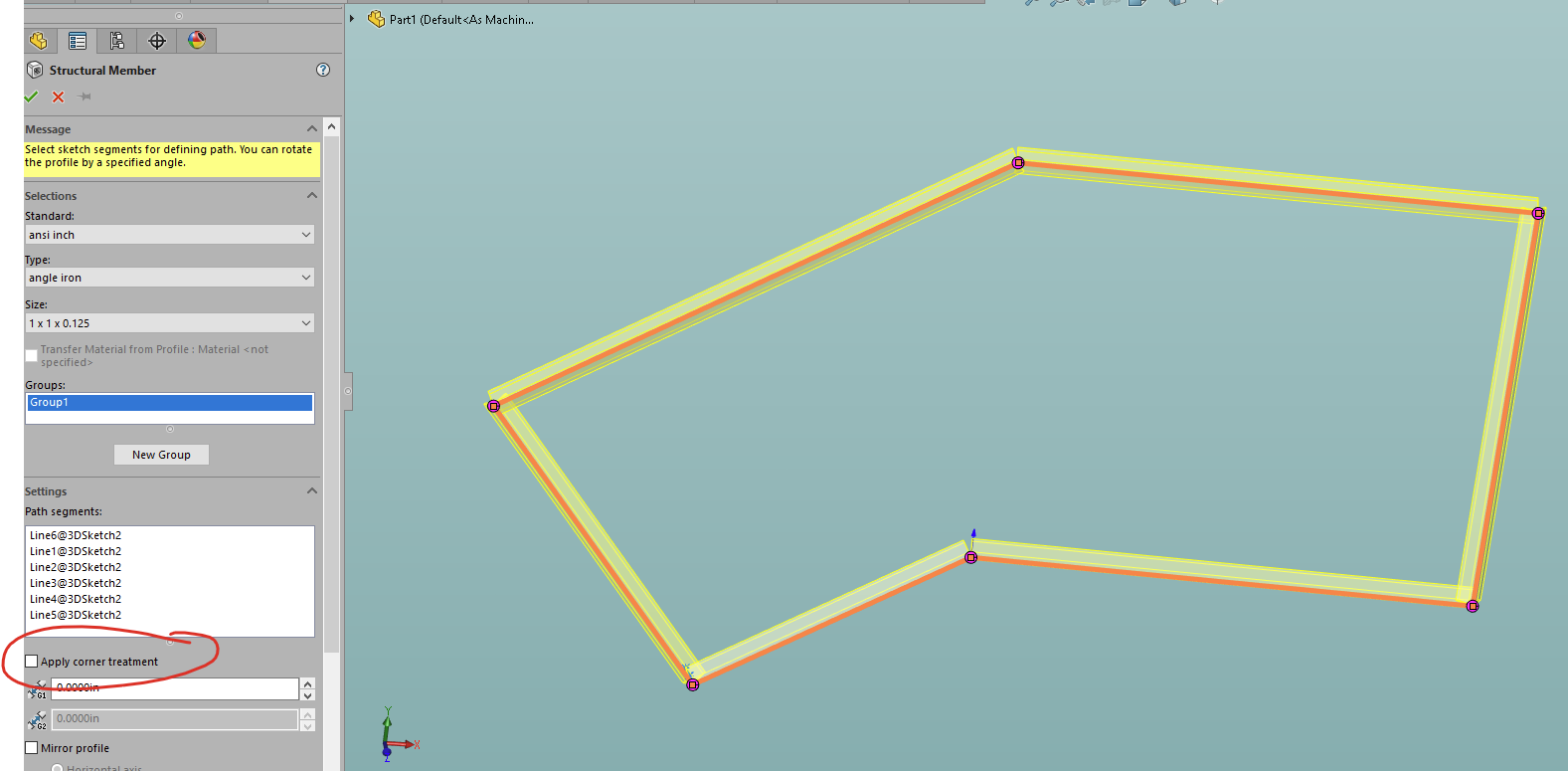
Honestly, the fastest way that I can think of to get this done would be to make it a weldment and add some random structural member (preferably the one with the smallest footprint).
Make sure that you uncheck “apply corner treatment”.
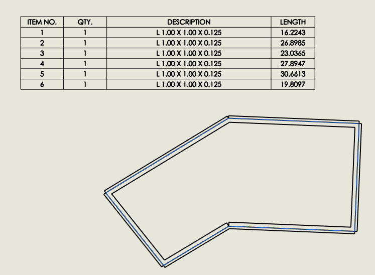
Then make a quick drawing of it and add a weldment cut list:
This will conveniently give them all the dimensions of each of the line segments.
You can even change the description (or create your own special structural member) to have some generic description so that they aren’t confused by the description that is shown in my picture.
1 Like
This is what I tried to achieve, but I had some dimension not showing up and I was not able to figure out the reason: I will try again when I have time. Probably I messed up with the order of clicks, your step by step tutorial will be handful. Thank you.
We have two provisional ways to handle piping: assy components and cut lists.
We use components for bending because we need to batch convert single files to feed our NC bending machine, so I made this nice macro that use basic 3d sketches and add bends radii and make a NC friendly 3D with a part list for shop guys. We have a system that check the pipe length against the blank and a “bent” or “straight” flag for the shop to sort how to make the pipe.
The problem is mainly with welded pipes and threaded fittings.
And hybrid piping with a mix of the three kinds. (bent, welded, threaded)
We have a fitting components library with a surface placed on the “thread end” on male female threaded connections and looking for a quick way to draw between those “end surfaces”.
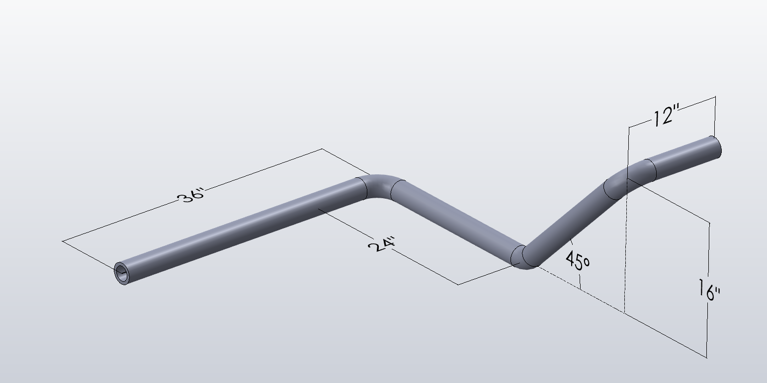
Take a look at the pic @JimSculley posted: assume it is a welded pipe and the elbows are actually components (they could be long or short, and 45° and 90° have a different radius so no shortcut to draw them all the same).
- I draw the basic 3D sketch without fillets, X-Y-Z lines (the diagonal 45 degrees line is also driven without angle dimension as it is easier to control with relations and equal construction lines along Z and Y)
- I put my fittings on the sketch: e.g. a elbow requires two concentric mates on the sketch line. A tee requires 3 concentric mates and so on.
- Copying with mates for each corner, switch fittings configuration as required to change the size.
- Now we have a base skeleton (3D sketch + basic fittings) and we need to draw the straight pipes between the fittings. This is where I would like to optimize the workflow.
I made a macro that draws straight pipes (virtual) components over a 3D sketch lines, but we need to trim them to match fittings around corners and intersections.
Option 1: weldment for straight pipes + trim?
Option 2: components with a new macro to draw straight pipes between 2 faces/surfaces?
Option 3: Draw a secondary 3D sketch on top of the first one to drive my current macro to draw straight pipes of the correct length.
Maybe I am overthinking and the solution is simpler, but I have the whole process in my mind including my shops complaints, my designer skills, I have to run (and fix) a whole PDM system (including its servers) and the company internal helpdesk and training (and occasionally asked to fix PCs and software the IT dep. is supposed to look after, and I am only a mechanical engineer  )
)
2 Likes