Yeah, I get it. Should have used purple again. I was just trying to get someone to take a swing. 
Oof. I should’ve known better than lecturing the author of Mastering Solidworks. <()>
(I’m reading it right now. Hats off to matt !)
I actually kinda like that the end points of “Convert Entities” lines aren’t restrained. It’s come in handy for me a number of times.
When creating or editing the Save Bodies feature, the file location for the new or newly edited body is the last file location you saved something in a SW session - Argh$@#!! I really think it should be the same directory as the master part file (which currently contains the Save Body feature) by default, then if you want to change its location, you can alternatively do that.
Edit to Add: I see you were being sarcastic from subsequent posts…I’ll leave this up though because it does explain this as intended functionality.
matt,
I agree this is unintuitive because it had to be explained to me. IIRC, they wanted to make this functionality “easy”. So when you convert entities those endpoints are linked to the underlying geometry but there are no coincident relations per se(they’re there but it doesn’t work the same as a “real” relation). Try updating the underlying geometry and the converted sketch will update accordingly (as long as you haven’t moved an end point). But if you move an endpoint it loses its reference to the underlying geometry and SW will correctly recognize the sketch as not fully defined. This is definitely one of those “consistently inconsistent” things in SW because it works differently than any reasonable person would expect, but AFAIK, it works exactly as they planned.
They’re meta-restrained…which confused the hell out of me when I first encountered it.
I prefer “Quasi-constrained” and its one my favorites aspects of SolidWorks that I haven’t seen in other CAD software. I just wish you could see a “coincident” in another color or have the ability to add it back once it’s broken.
Here’s one from today - a sheet metal box with a bottom and four sides, all sides the same height, four sketches for the sides, each sketch with its own height dimension.
Dwight
I love the way SW from time to time jumps from my right monitor to the left monitor without cause, without warning.
Yep, happens to me often as well. It’s always a guess where any Solidworks itself, or any of the sub windows, will pop up.
But then again what do you expect from programmers that can’t even make toolbars actually stick to the place you put them. Something that even barely functional acad clones back in the 90’s could do.
 ..amazing how many “fully defined” meme’s are on the web!
Came across this today
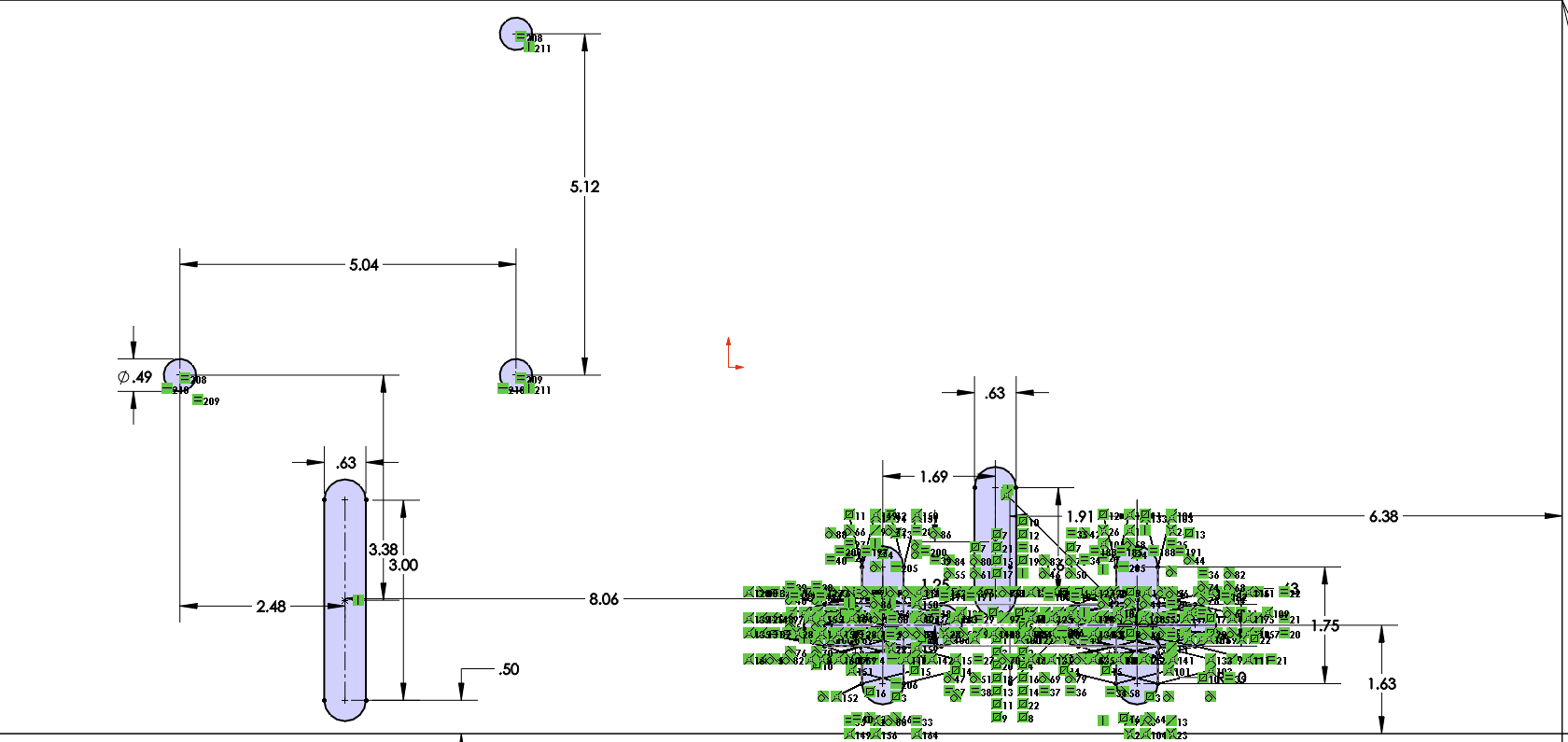
Please, please don’t put everything in a sketch and don’t use sketch mirror for a large amount of lines! 
 <()>
<()>
Unfortunately I can’t blame mike miller for this one!
How in the world can you even get that many constraints on so few pieces of geometry? I would actually give a gold star for most redundant restraints without creating a constraint conflict.
It looks to me like someone needs to be educated about the benefits of the Hole Wizard feature.
I guess I could have used the hole wizard but it didn’t seem like the right feature for the application.
So I ended up making the “x” slots a separate cut, sketching the 2 lines and arcs, doing a sketch circular pattern, doing a linear pattern of the Cut feature, and done, fully parametric!
image.png
image.png
Another pet peeve of mine is sketch bends, especially if an edge flange could have been used. They fail easily and their just a pain…
I take it back. You’re right about the Hole Wizard not being right for that. I didn’t realize those were + shaped cuts. I didn’t see the horizontal portions since they are almost completely hidden by the relation icons in the screenshot.
I hate it when people attach useful videos and files but I am unable to access them. What setting do I need to change to fix this.
Case in point:
So I ended up making the “x” slots a separate cut, sketching the 2 lines and arcs, doing a sketch circular pattern, doing a linear pattern of the Cut feature, and done, fully parametric!
image.png
image.png
This is a method that I sometimes like to use -
image.png
Draw two slots
Make them equal
Add locating/sizing dimensions
Select contours when making the cut
t
The server or something hiccupped a few weeks ago and all attachments were lost. matt can probably explain it better; I mean he can definitely explain it better.
Ok, no problem, I thought that was behind up but I guess these were posted before that.