Same for me in 2020 SP5. I don’t see anything in the help that talks about this workflow either.
Tom
You are right. I had thought I’d seen that done in a presentation, and I have occasionally used saved section views, but I never did use one in a drawing. I see now that help does say that you can’t use them in drawings.
Sorry for the misstatement.
Dwight
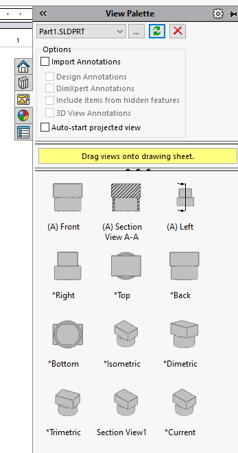
I don’t know where in Help it states this, but section views saved within a model can be used in a drawing and are dynamic to changes in the model’s section view. To do this follow these steps:
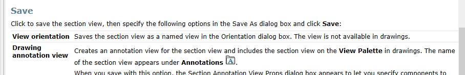
At the bottom of the section PM, click Save:
image.png
This dialog displays with “Drawing annotation view” not checked:
image.png
Check “Drawing annotation view” and the name automatically changes to the “normal” section naming.
You can change this, but I usually don’t. Also, for each save, this name will increment the section letters.
Also, if you don’t uncheck the first tickbox then this view will also be saved within the model (available on the Orientation dialog):
image.png
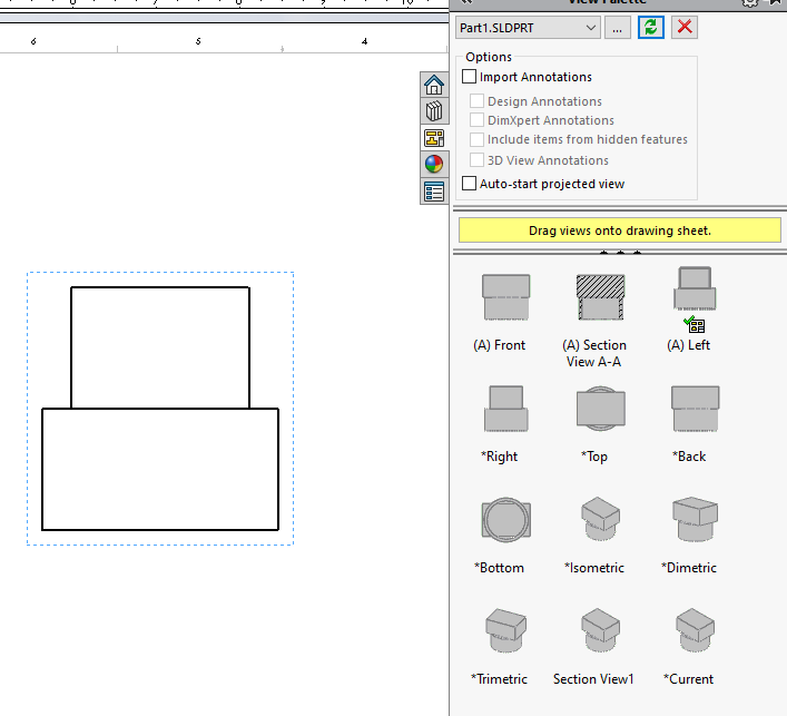
Save your file and in the drawing refresh the views, if needed, and you’ll see a cutting line view and a section view for each saved section:
image.png
The caveat is that you must place the cutting line view onto the drawing before placing any saved section view.
As you are dragging the cutting line view onto the drawing, the cut lines will be visible, but after you place the view, you won’t see any cut lines in the view. This is normal. These will show later.
Also, the cutting line view is no longer in the view palette:
Drag each saved section view from the palette and onto the drawing.
As each of these views is placed, its cutting line will automatically be shown in the parent cutting view:
You can always just create a second configuration in the Assembly, make a simple extruded cut that’s suppressed in the main configuration, and use this configuration as the section view in the Drawing.
Unless the section views are saved as a “Drawing annotation view” (as I showed in a previous post) then these views will not be available in the drawing view palette.
This method has worked for me for parts and for assemblies.
Yes. In help it states that when using “View Orientation” the views cannot be used in a drawing. As you say, using "Drawing annotation view " does work.
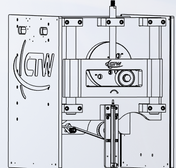
I am still struggling with this. I create the section in the assembly. When I try and add the view in the drawing, it changes the orientation, and flips the direction of the section.
This is what I want to see:
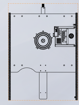
This is what I can do in the drawing:
Orientation correct, no section:
or
Normal to section, and facing the opposite way.
I have done this in the past by making a cut extrude in the assembly and saving that as a configuration with the cut unsuppressed, then you have your section view available for any orientation you want.
Why are you trying to do this from the assembly..? Is it for the 3D orientation? I’ve never seen section views created in a part/assembly be brought into drawings. (Not that I think it’s wrong, I think that could be pretty cool actually)
The occasions I’ve had to do something a bit more precise, I did it as TTevolve said.
Yes. I wanted the view off axis in the drawing. I think TTevolve has the right answer.
I have done cut away sections this way as well, you have more control over the depth, plus you can orientate the isometric view however you want without your sketch moving like it would in the drawing section/cut away view.
I also think it’s easier to suppress parts in the the assembly configuration than hiding them in the drawing views. Down side is you have configurations to deal with.
1 Like
You can create a normal section view in the drawing, then right click the new view and select “Isometric Section View”. Downside is you need a parent view and you can’t really control the orientation or angle of the view too much so might not work for every case. I like to avoid adding stuff to the model needed for the drawing if I can help it, but sometimes you have to do what you have to do.
Today, I can’t create a section view in the drawing without solidworks crashing.
Every day I waste hours trying to do something that should take seconds, the pain of switching to a different software package seems less and less important.
Try creating it on the side of the view to see if it works, I’m not sure what could cause this.
The only thing I can figure is that there is something in the assembly making it unhappy.
Only happens in this assembly? If so, any special geometry in that logo? Any parts in prior SolidWorks versions? That’d be the things I’d look into.
It doesn’t matter. In typical SW fashion, I’ve bashed my way through enough to get what I needed done. Unfortunately I don’t get paid for doing it right, or debugging SW. As long as I’ve generated the information I need to convey to my co-workers, I need to move on to what is next.
I’m really getting tired of fighting the tool that is supposed to help me.
Did you try sketching a line in the view first, selecting it, and then inserting the Section View (the old school method, which I still use exclusively)?
2 Likes
No. I wasn’t aware that was an option.
1 Like
It is an option. When I started using SW that was the only way to create a section view in a drawing. First you sketch the line (making sure the drawing view is active), exit the Sketch function, select the Line, then go to Insert > Drawing View > Section.
By the way, if you sketch the line from top to bottom the drawing view will point to the left by default. If you sketch it from bottom to top it will go to the right. You can of course reverse it in the view’s property manager if you want.
I believe something similar is true for lines sketched horizontally or at an angle, but I use those so seldom that I’ve never investigated the behavior.
1 Like