Same thing with ancient PC.
No drivers for new printer. Try to find one with parallel printer port. Even one with USB port may not work.
New software? Unless you can program it yourself, no way.
Get on to internet? More like a inter-wall
I don’t miss the days when anti-virus updates came in mail on floppy.
You could download old app installations for iPhone and Android, if you know how and where to look.
Might need Jailbreak and Root.
Just like you keep all those floppies.
Floppies…now that is ancient. I don’t have any PCs that old but I do have some 10+ years old, one running a PDM test vault.
Back to the ipad, it’s 10 years old. I just want to run the old software that was available for the device at the time it was current. Nothing fancy and its still a good and fast device with the few apps on it. I shouldn’t have to “jailbreak” it. I just want to install old apps on it like an mp3 player or book reader, pdf reader, etc.
It’s an apple product. They’ve always told you how you could use their hardware. The disappointing part is that microsoft has now adopted the same model.
Apple and Google only keep updated apps on App Store.
And they all built to specific OS versions. Old app won’t work on new OS. New app won’t work on old.
I can get Android App install package and run it to install.
Don’t know if it could work on Apple. They might have blocked app install out of AppStore. Hence jailbreak required.
Apple don’t want Grandpa installing bank draining App from email and sue Apple.
Jailbreak it and it’s your problem.
Jailbreak, root is to unlock all protection so you can do anything you want. Legal and illegal.
Old Windows came with no such protections.
I hate hackers and evil people in the world. Ever since our company decided to open our networks to global teams and vendors… I have to “authenticate” multiple times a day on my phone. I feel like I’m wasting 5% of my day playing authentication roulette every single day of my working life.
image.png
The hackers keep finding ways to get around it. First my password had to be 8 characters, then 8 characters with upper and lower case. then 10 characters, then 16 characters with at least 2 uppercase, 3 lowercase, 2 numbers, 6 symbols, 2 dwarven runes, blood type, with no English words or l33tsp34k.
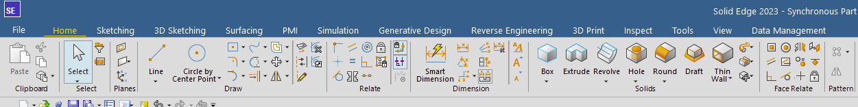
The 2023-2024 Solid Edge interface. Just started using it and it’s >>>
Everything is so close to the same color
If only the marketing team wouldn’t have gotten ahold of the interface…
I’m getting used to it though…
I read a while back they were aligning icons with NX. I wonder how many users that actually helps; how many use both systems and need the icons to look similar? I mean, they’re vastly different systems, why need same icons?
It’s bigger than just SE aligning to NX or vice versa… All Siemens PLM products are aligning to a consistent UI Standard which includes SE, NX, Technomatix apps, Simcenter apps, Teamcenter, Electrical products and the cloud apps (Share, Zel X). The idea is that if you want to use the “Window Area” command for example, it is a consistent icon across all products and the products all have a consistent look and feel. Some companies use multiple Siemens products, and a single user will have to do similar functions in all of them. You will see a mix of icon graphics coming from a variety of the apps as they are standardized.
In regard to Solid Edge AND NX, they are not “vastly” different. Both have the same fundamental MCAD commands and thus have a large command overlap. Apparently, there is a large subset of customers who use both interchangeably as Siemens sells a Mechanical Design Bundle that includes both licenses. Also, if you use SE with SE CAM Pro, SE CAM Pro is actually NX.
Joints in Fusion 360 make no sense. How can you take something as simple as mating two components and make it so convoluted a person can’t figure it out?
They’ve adopted a DSS type attitude of solving a problem that didn’t exist, and then digging their heels in saying, “but its better, you just don’t get it.”
8 years later, and I still can’t figure out how to mate 2 components together.
When we started Fusion, one of the areas that we decided to try to improve over more traditional CAD software was the area of assembly modeling. Customers new to CAD often struggle with such abstract and mathematical concepts as “flush” and “mate” for describing relationships (especially kinematic relationships) between components. So, we decided to try to elevate the concept a bit to terms that are more familiar to mechanical designers: Joints. In our thinking, a “revolute joint” was more obvious than “Mate” between two linear entities that just happened to result in a circular degree of freedom. So, we decided to go “all in” on the joints approach, and not offer traditional assembly constraints at all. It was a bit of a risk. To our knowledge, no CAD software had tried this joints-only approach to assembly modeling.
In our (admittedly biased) opinion, this works very well for describing kinematic relationships. It seems pretty easy to created jointed component relationships. Especially in a top/down workflow, with “As Built Joint”, I find it really easy to create most common mechanisms.
In the interest of honesty, where this approach still requires some tuning is in trying to position components rigidly with respect to each other. Fusion has always had Rigid joints, which definitely solves part of this workflow. But the joint positioning choices didn’t always result in exactly the correct relative positioning of components relative to each other. So, over time we have added a few commands that help. One is Rigid Group. This command allows you to select a set of components and make them rigid with respect to each other in ther current positions. The Align command allows you to position components with respect to each other, by aligning geometry, and Move allows you to do more freeform moving of components. So, a very useful workflow is to use Align or Move to position components, then put them into a Rigid Group.
The other workflow is one that works well with top/down design. If you create components in a top/down design manner (for example, one sketch that is used to create 3 components), and you build these components in the orientation with each other that you want, then a simple As Built Joint with a type of Rigid works very well.
We are always looking for ways to improve workflows in Fusion. If you have ideas in this area, please let us know.
It’s the other way to “innovate”. Take something that already exists (spatial relationships) and couple it with an idea that few use (kinematics) and BOOM… a new innovation was born! Then defend it because otherwise there is nothing new.
Example: It’s no longer a turning indicator, to simply indicate if you intend to turn left or right on your car. We have combined it with the compass and it’s now a directional indicator that will indicate whether you are turning North, South, East or West in relation to your current direction of travel
I’m reviewing a report. It has “five feet tall,” “9 feet tall,” and “180 inches” IN THE SAME SENTENCE. So let’s just arbitrarily spell out some values and use the numeral for others, and throw in one relatively large dimension in inches while smaller ones are given in feet. To top it off, the one in inches is shown as feet in the drawing, so the writer had to do math to come up with the value for inches.